12 Squared 1/72 Gnat 750


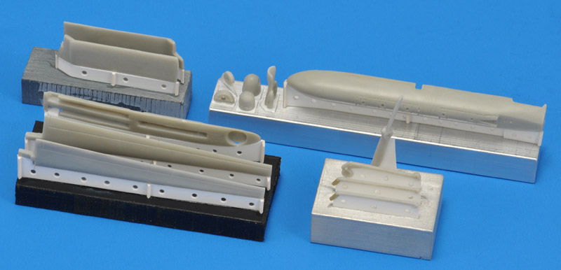
For years I tried to find the 12 Squared General Atomics Gnat, to add to my slowly growing collection of 1/72 unmanned models. In many years of weekly Ebay checks I never saw one, although one was offered and sold so I learned afterwards. In 2007, I finally obtained one through Tom 'MAI/ESM' Young. Many thanks Tom! Unfortunately, I learned that Tom left us in May 2018, see his obituary.

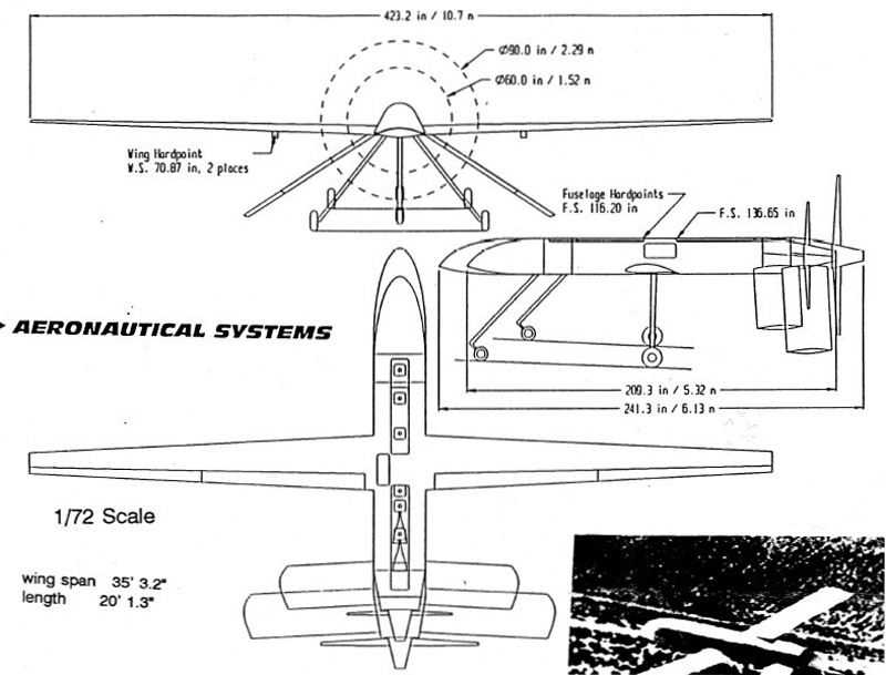
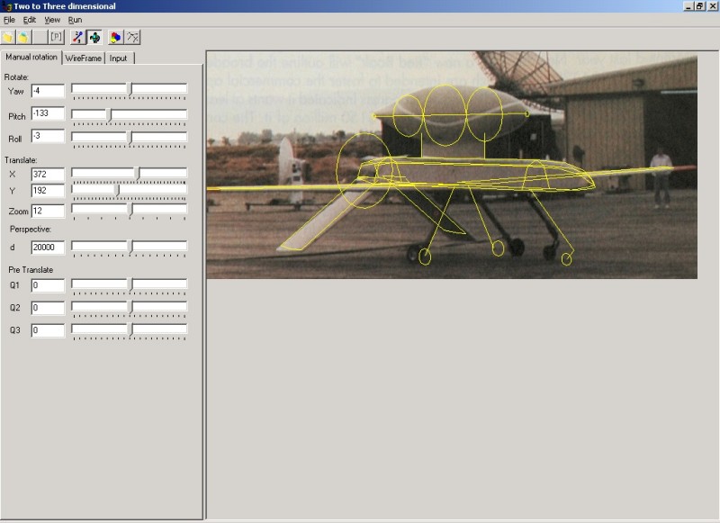
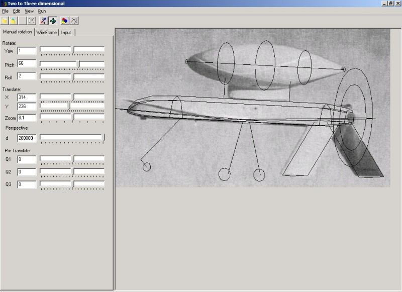
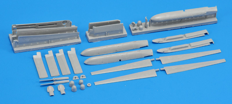
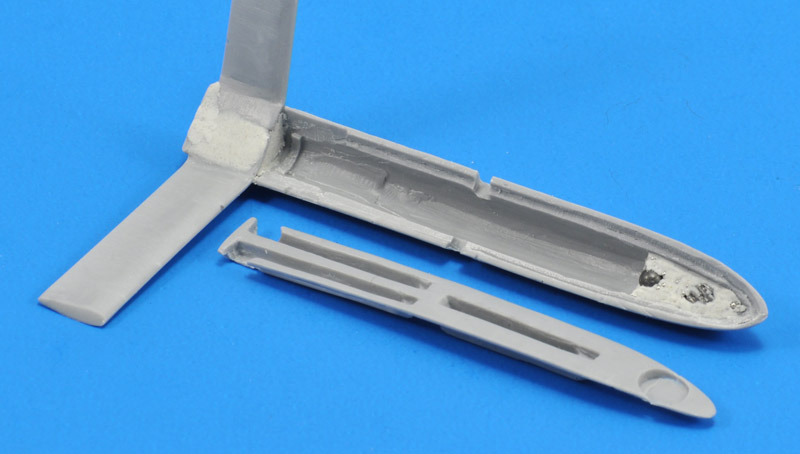
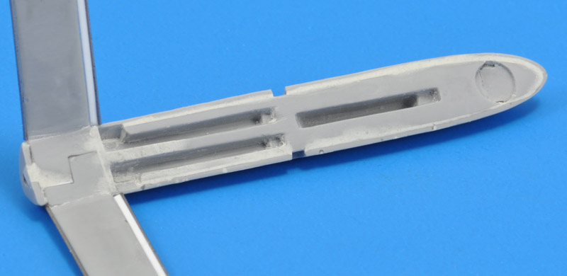
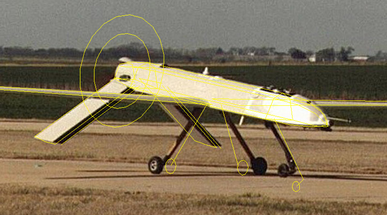
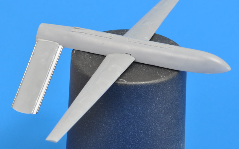
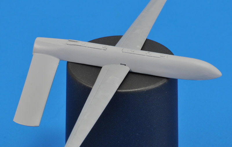
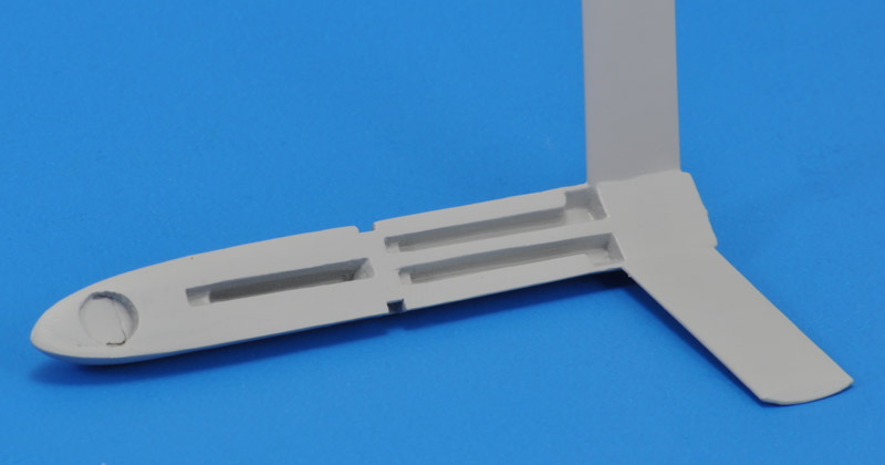
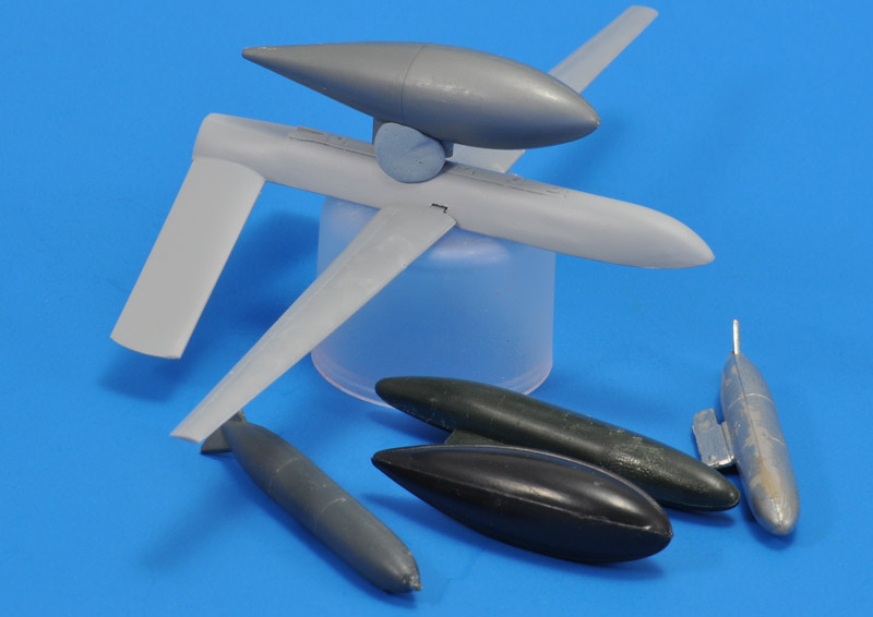
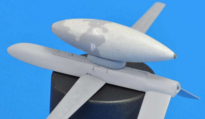
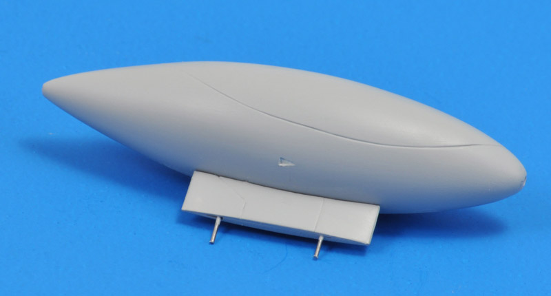
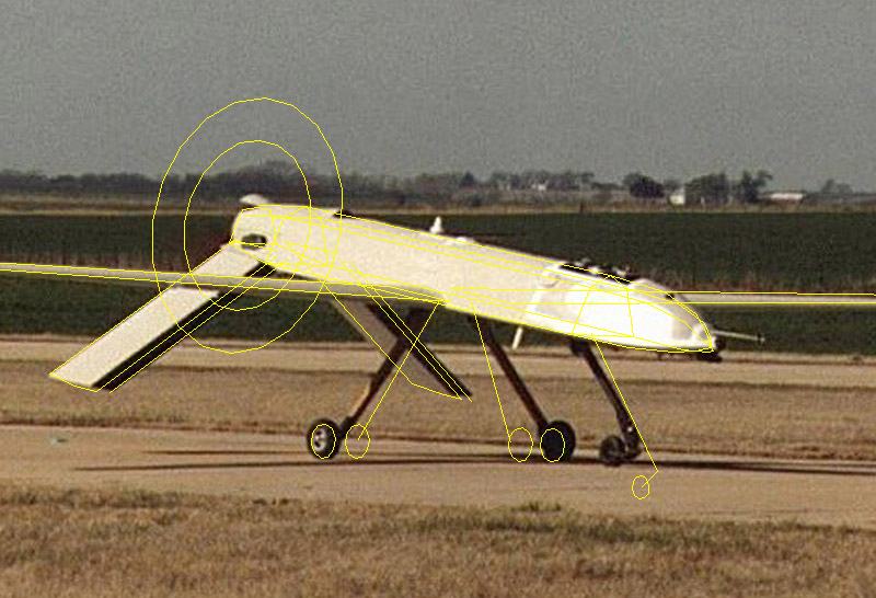
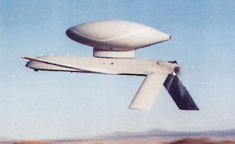
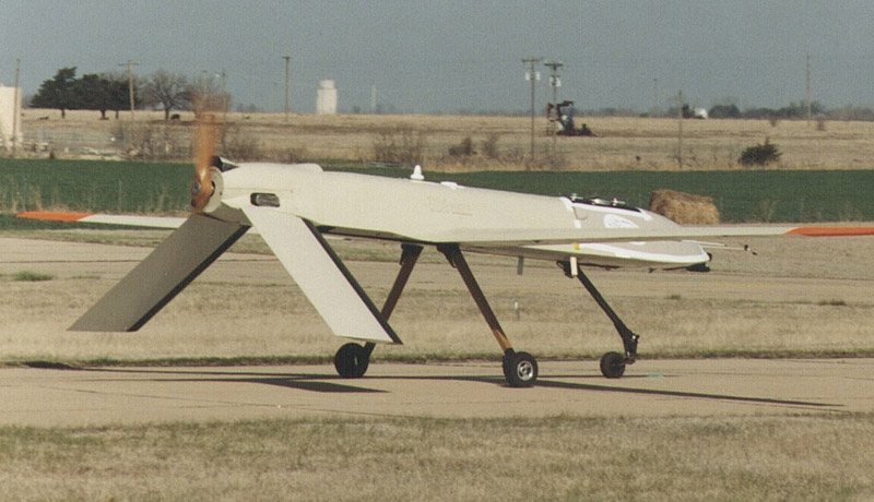
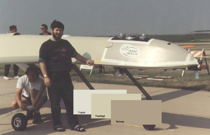
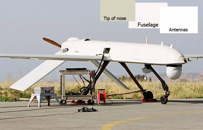
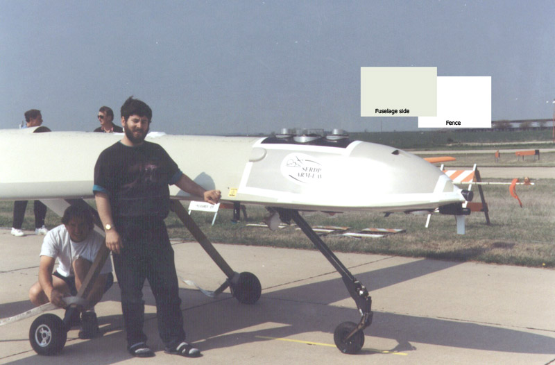
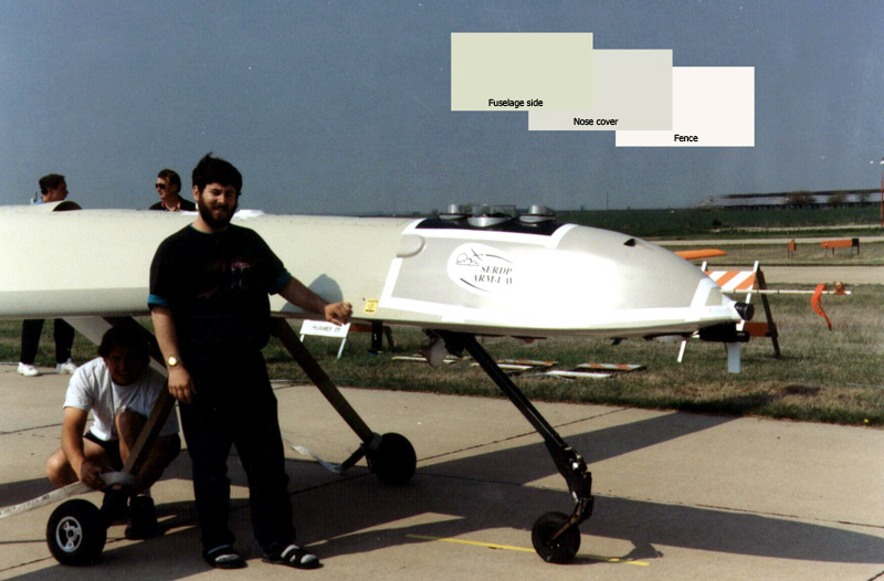
I would call this build an 'exploratory' one. My knowledge of the subject is limited, and there's a lot to be discovered. The things I notice in time will be corrected on the model, some others won't. It will never be a perfect model. I decided to build the General Atomics company Gnat, used to develop a UAV with satcom capabilities, around 1993. A giant radome was put on the tiny Gnat, somewhat similar to the satcom radome seen on U-2R/S aircraft since about 1990.


Model description

Some comments:

I found just a single built example of this model on the internet - amazing! Alain 'Colossusfr' built the 12 Squared model and shows it on the BritModeller and Maquette 72 (French) / (translation) forums.

Richard Koehnen, 12 Squared owner, reported that he probably produced less than 200 Gnat kits. It was probably issued in 1997.


Are real Gnats long or short?

The 12 Squared instructions include a nice drawing, with two versions: with a short and a long fuselage. The 12 Squared model agrees with the long fuselage. But it fuelled the question whether photos of the real thing showed the short or long version, or possibly both? That question bothered me for a long time, until I found the time to translate the drawing into a simple wire model, that could be laid over a photo using six degrees of freedom plus perspective.
I'm using a custom-made piece of software for this purpose, that was written by Tjarko de Jong. A big thanks again!

It's a laborious task to align the wire model with the aircraft in the photo, with three rotation angles, three linear displacements, a zoom function, and lastly a viewing distance parameter that creates perspective. The latter is really important, since most photos are made with relatively short lenses, that create an amazing amount of perspective. We're so used to seeing deformed objects that we hardly notice it - until you try to align a wire model without perspective over a photo!

Here's the first Gnat photo that I tried to analyse. I think the results are convincing: the wire model of the short version can't be made to fit. It fits like an oversize coat.
The long version fits almost perfectly - it's almost amazing. Other observations are that the main landing gear legs is splayed out in the photo. The nose leg is definitely modeled too long and too far forward. The prop diameter is difficult to judge.
A second photo (of very low resolution) was also analysed. Again the short version cannot be made to fits properly.
The long version again fits like a glove, although the wing bends a bit due to flight loads. It is now also clear that this one used the smaller 60" propeller.

My conclusion is that the 'long' version of the drawing is the standard Gnat-750. I have never seen a Gnat photo that matches the short version of the drawing.

It's a pity that there are no decent in-flight photos that show the wing plaform clearly. It would be nice to check the drawing's wing planform with photos.


Satcom radome analysis

The Gnat that I want to build was a special General Atomics development for the CIA, allowing satellite communication. It had a huge satcom radome fitted on the fuselage.

To establish the radome's measurements, I used the wire model again. With trail and error I defined the axis of the radome, diameters at various stations, plus the leading and trailing edges of the pylon.
I overlayed the wire model on a second photo too, showing that a bit of tuning is still required.


Copying

This model is very rare - I never saw this kit on Ebay in many years of weekly searches. It really stopped me from building it. After some deliberations I decided to cast a silicone rubber mold.

Shown here are all the parts mounted on their casting blocks. I had only one usable main wheel, so I'll have to cast that multiple times.
I made three sets of castings, with one set still attached to the molding blocks. I did not copy the prop axis, it was too rough and easily replaced.
The spindly landing gear legs were strenghtened with spring steel wires (first 0.75, then 0.5 mm). The legs of the second casting failed, most wire inserts were placed wrong (right).

Let the building begin!


Construction

The model's construction can be approached in different ways. I decided to start with the inverted V-tail, to be assembled from interlocking parts. I don't have solid data on the angles, but measured 55 degrees anhedral in the drawing. I made a simple drawing to align the pieces, and flowed CA glue in the joint. I could have used the included front view drawing too, but I did not want to risk spoiling it with CA glue.
Next I glued the tail assembly to the upper fuselage, while having the fuselage level on steel blocks, and a 2 mm spacer under the tips of the tail surfaces. I used tip-of-the-nose to tip-of-the-tails measurements to ensure a square fit.

Only afterwards I noticed that the fuselage height tapers slightly towards the rear, something that the original does not have, I believe. I measured 7.1 mm at the front, and 6.6 mm just ahead of the tail surfaces.
Making the bottom fuselage fit into the top fuselage required a lot of cutting and scraping. And pretty substantial gaps are then still left. But that all comes with short-run territory - nothing that a little Apoxie can't solve.

Talking about Apoxie: I used a bit to fill the area between the fuselage and tail surfaces, to make sure they will never fall off. For balancing, I glued some lead balls in the nose, again using Apoxie. To make room for that, the lower fuselage was aggressively scraped to thin it.
The gaps were filled with Apoxie, but the lower side still looks off. All gear wells are displaced some 0.3 mm to the left - that sounds like nothing but you spot it easily. Maybe with more scraping, the lower fuselage could be installed correctly. The three landing gear openings can be narrowed, since most of the openings are sized for the thin legs only.

Also, the belly is flat whereas it should have a shallow V-shape, just like the Predator. Maybe it's better to build a new fuselage from Platz/Italeri RQ-1 parts?
The tailplanes looked 'off' by quite a big margin. I first compared them with the kit supplied drawing. The chord agreed, the length (span) probably is 1 mm too much.

Next I dusted off the old 3D-line-drawing-over-photo software. I added an extra line ahead of the tailplane's leading edges, and moved it until it approximately agreed with the photo. That new line was 150 mm further forward, so I need to increase the chord by 2 mm. That is substantial. The chord is now approximately 780 mm in my wire model.

The analysis should be repeated on other photos, before a degree of certainty can be established.
First the tailplane lengths were reduced by about a millimeter. Their span now agrees with that of the Platz Predator kit, if that means anything. Then the tailplanes each got an 0.5 mm steel wire on the trailing edge, and a 1 x 0.5 mm plastic strip plus an 0.5 mm steel wire on the leading edge. I should have used a 1.0 mm wire on the leading edge, it's too sharp now. The chord differs substantially from the Platz Predator kit, if that means anything.

Although the model now looks more realistic, the size of the tailplanes is immense compared to the high aspect ratio wings. In most real life photos you don't see both at the same time. It's a bit of a strange design.
After a few rounds of filling and Tamiya Surface Primer, the tailplanes looked decent again. I still need to visually separate the tailplanes from the fuselage.
The lower fuselage with a layer of Tamiya Surface Primer, showing the slight slant of the wheel wells. The flat area between the tailplanes needs substantial reshaping, ending in a cilindrical cross-section at the rear.
My wire model had given me the main dimensions of the satcom radome: 15 mm diameter, 56 mm length. I checked my spares box, and found a few tanks and bombs that could work as a starting point. One was particularly suited, and it's placed on the fuselage with some Blu-Tack. But it's only 13 instead of 15 mm diameter, and a few mm too short.
First I wrapped 1x1 mm plastic strip around the tank, but slightly too far forward, the widest point is in the middle. I glued a steel paintshaker ball from a Mr Paint bottle to the nose. Then it was time to mix a lot of Apoxie, and careful sanding after it cured. When it started to become round, I switched over to a Flexi-file. The next layer was Mr Surfacer 500 from a bottle, followed by more Flexi-filing. I installed a 1.1 mm Albion micro tube in the tail of the radome, and drilled a 0.9 mm hole in the steel ball in the nose.
Tamiya Surface Primer was next for the radome. The pylon measurements were taken from the wire model. I built it up with three layers of 0.5 mm plastic card, with two full length pieces on the outside, and a short piece inside, to create a nice aerodynamic shape. 0.5 mm spring steel wire ends were added to create solid leading and trailing edges. The same wire gage was used as aligment pins that went into the radome and into the fuselage.
I tried finding a simple method to transfer the panel line shape to the radome, but I ended up using a fairly involved method. It required a jig that I built from Lego blocks. I drilled some holes for 0.75 spring steel wires in the Lego, and used the cooling air openings in the radome as mounting and rotation points.

A paper tube with printed 20 degree intervals was used to draw short longitudinal lines on the maximum diameter section of the radome, that were then extended from nose to tail using an 0.5 pencil lead, guided by the jig. Next I used the same jig to draw circumferential lines at 5 mm intervals.
I used my 2D side view to find coordinates of the panel line. For each 5 mm interval, a cross section was drawn, and the angle from the vertical of the panel line was calculated. Not shown are the four cross sections of the rear half.
Next I sketched my measurements on the grid on the radome. A 1 mm wide vinyl tape was used to connect the points, and used as a guide to scribe a panel line.
The end result, with small NACA inlets engraved after the last layer of Tamiya Surface Primer.


Again measuring from the included drawing, I measured ~4.5 degrees between the left and right lower wing surfaces, and ~2.5 degrees between the top wing surfaces. Since the chord line is much closer to the lower surface, I decided on a 2 degree dihedral angle.

Since each wing half is 69 mm, it required a 2.4 mm spacer under the wing tip during gluing.
The main gear legs definitely require a jig to attach the fuselage. Doing this freehand cannot lead to an acceptable result, I'm sure of that. I used some Albion microtubing that slides over the wheel pins, and a piece of plastic profile to align the tubing pieces.

The 12 Squared Gnat main gear legs have exactly the same length as those in the Platz Predator. Since they have nicer detail, then could be nice replacements. But I would have to recast then with steel wires inside.
Another detail that required attention is the splaying of the landing gear. I added 'extra' wheels to the wire model, that were moved outboard until they more or less agreed with the photo. 400 mm was required per side, making 5.6 mm in 1/72 scale. My neat little main landing jig needs rebuilding.

Don't mention the nose gear now.

Kit prop is ~32 mm, which corresponds with the 90" prop in the kit's drawing. But most photos show a 60" prop installed (21.2 mm). Maybe I'll replace it with a modified Platz RQ-1 prop, that is ~23.5 mm diameter.


Another fuselage

I always wondered whether the RQ-1 Predator fuselage was identical in cross section. I had no actual data to support that, so I decided to simply give it a try. I obtained the Italeri rebox of the Platz Predator. The modification process was largely improvised, lacking good drawings, finding a route along the way.

The upper fuselage has a constant cross section from the small antenna slot aft, so I cut it there. The front part can be discarded. On the center/rear part, I removed the wing root fairings.

I cut the lower fuselage in five parts, of which two were discarded. The Platz Predator has very shallow wheel wells, that I couldn't leave alone; see the next photo.
Using a JLC razor saw I removed the roofs of the two wheel wells. I left the wheel opening intact for the time being, to avoid creating an extremely vulnerable part. The well sides were built with 0.5 x 0.5 mm strip, covered with some 0.35 mm plastic card sheet. All edges were rounded off to make things fit inside the upper fuselage, that needed additional scraping itself too.

With strength restored, I glued a 1 x 2 mm 'spine' over the wheel opening, then cut away the wheel roofs. Another piece of 0.35 mm card was used to create a new roof.
Using photos and the 12 Squared model, I moved the lower fuselage 8 mm aft, using the small NACA duct as my reference. This move also required some plastic to be removed on the upper fuselage, since the wider part of the lower fuselage requires more space.


Colors and markings - attempt 1

In photos I see a slightly brownish grey color. The color reminds me of my old Commodore 64 computer, and probably a light version of the RAF color 'Camouflage Beige' aka 'Hemp'. Browsing through my FS595B fan deck, I noted the following possibilities: 36555 p47 (too dark?), 36586 p45, 37769 p43, 36642 p40, 13578 p6, 16555 p6, 13522 p6
This Gnat has the same color I think, and it somewhat matches the concrete of the taxiway.
Another view of the same aircraft, with different color references, like the white T-shirt of the man below the wing. I made color swatches of three areas.
Another photo, that shows antennas on the nose that are close to pure white. The fuselage shows a very light sand color. And interestingly, the very tip of the nose shows the darker and browner color that I see in the above photos.

No markings it seems.


Colors and markings - attempt 2

Opened the photo
Opened the 'Curves' panel, and used the 'Sample in image to set white point', using the white parts of the red-white fence. The change is substantial.

I cannot find a way to set the pure white parts to FS 18785.
The color corrected photo, sampled on the fence and fuselage side. I keep seeing a sand-gray color, and not a pure gray. However, the Gnat is less yellow that in attempt 1.


Colors and markings - attempt 3

I used 'Sample in image to set white point' AND 'Sample in image to set black point' this time.
Now I see two distinct colors on the Gnat - interesting! The nose cover is a neutral gray now. But the majority of the airframe remains a sand-gray color.


Colors and markings - attempt 3

The sand color makes me think of US utility equipment that is painted similarly, like this air-conditioning unit.
Here's another airco unit in the same color, but with different light conditions.


Links


Return to models page